
Using CFD to Optimize Auxiliary Power Unit Design

Hamilton Sundstrand, a subsidiary of United Technologies Corporation, is among the largest global suppliers of technologically advanced aerospace and industrial products. Headquartered in Windsor Locks, Connecticut, the company designs and manufactures aerospace systems for commercial, regional, corporate, and military aircraft, and is a major supplier for international space programs. Hamilton Sundstrand Power Systems, located in San Diego, California, designs and manufactures APUs, high-performance fans, and other environmental control equipment. The company provides a wide range of APUs for commercial aircraft, from business and regional jets to 200-passenger airliners. More than 3,360 of these units are in commercial service with over 26 million hours of operation experience.
Power on the ground and in the air
An APU is a gas turbine engine, started with an electric motor that is powered by batteries or the aircraft's electrical system. The vast majority of APU use comes while the plane is on the ground where it supplies electrical and pneumatic power for normal ground operations. An APU must be capable of starting in the air as well, however, because its secondary role is to supply emergency electrical power. In the design of the APU for Embraer's ERJ 170, Hamilton Sundstrand faced some unique challenges. Typically, the company supplies the APU and does not get involved with the design of other parts of the aircraft. But in this case, the company was asked to design the air inlet for the APU as well. This component is between the aircraft skin and APU itself. "It was a particularly challenging component to design because there were constraints regarding size, drag, and acoustics," says Jose Goldstein, senior engineer at Hamilton Sundstrand Power Systems.
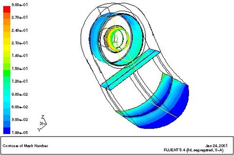
Figure 1: This figure shows Mach number contours at four locations: the inlet to the duct, the muff inlet, the screen, and the bell mouth inlet. The intake loss is the average total pressure drop between the duct inlet and the bell mouth inlet.
One of the design goals was for the inlet to be able to achieve the level of pressure recovery necessary for compressor operation. The challenge was to minimize the loss of pressure from the air entering the inlet by recovering part of the dynamic pressure and converting it to static pressure. Some additional design features, such as the de-icing fence, air inlet splitters and screen, further increased the difficulty of the analysis. The purpose of the fence is to keep substances such as snow and deicing fluid from entering the APU while the plane is on the tarmac and during take-off. The drag effect of the fence causes the boundary layer of the incoming flow to separate before it enters the inlet. Depending on the location of the fence, the boundary layer might not have time to fully reattach before reaching the compressor. If this happens, the static pressure in the fluid is too low to achieve the necessary pressure recovery at the APU inlet. Inlets often contain flow splitters or guide vanes to help direct the flow of air. Hamilton Sundstrand Power Systems wanted this inlet to have thick guide vanes made of a noise attenuating material to meet customer acoustic requirements. The numbers and the location of splitters will affect the flow distribution. Downstream of the inlet is an area called the muff, an aerodynamically-shaped plenum which includes a perforated metal screen that makes airflow more uniform before it enters the engine's compressor, as well as protecting against foreign object damage. Correctly modeling the screen is another challenge for the CFD analysis
In the past, if Hamilton Sundstrand had been asked to design this inlet, engineers would have relied upon their experience to satisfy the pressure recovery objective while balancing the many design variables—inlet geometry, fence configuration and location, and the number and position of guide vanes. They might have taken advantage of wind tunnel testing to evaluate the design, but wind tunnel testing is very expensive and the information that could be obtained for this purpose is limited. "When aircraft manufacturers do wind tunnel testing, the APU inlet is covered," explains Gao Yang, Master engineer at Hamilton Sundstrand Power Systems. ".The test data is generally not obtained with any flow through the APU inlet, which is very different from the condition we need." The other alternative for verifying the inlet design was a flight test. Any problems discovered at that point would have set back the date for the finalization of the design and could have delayed production of the aircraft. The cost penalty for delays at this point in the process would have been severe. "It is enormously expensive to change something such as the location of the inlet at that point," says Jose. "Any change we made to the inlet geometry would affect the entire tail section, requiring it all to be structurally analyzed again and possibly retooled."
The need for a less expensive method of determining inlet pressure that could be used before the first prototype was built led the company to look into CFD. A CFD simulation provides values of fluid velocity, pressure, temperature, and other relevant variables throughout the solution domain for problems with complex geometries and boundary conditions. As part of the analysis, a researcher may change the geometry of the system or the boundary conditions and view the effect on fluid flow patterns or other variable distributions. CFD also can provide detailed parametric studies that can significantly reduce the amount of experimentation necessary to develop a device and thus reduce design cycle times and costs.
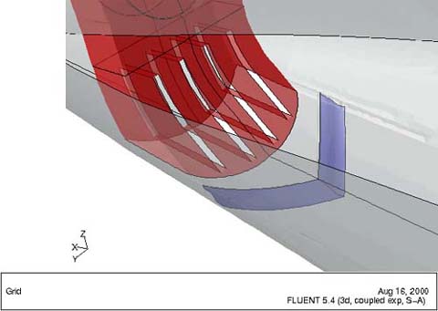
Figure 2: HS 2: This CFD drawing show the inlet duct with its four splitters and one turn-vane.
Hamilton Sundstrand Power Systems uses the FLUENT CFD program from Fluent Incorporated, Lebanon, New Hampshire. One reason they selected this package was because the solver is robust and supports fully unstructured meshes. In addition, the preprocessor, GAMBIT, greatly simplifies the creation of these meshes. For example, GAMBIT has tools for creating a very fine mesh around small, critical areas and allowing the mesh to progressively coarsen as components get larger. Because the scales of the geometric components vary greatly in aerodynamic applications, creating a mesh without the GAMBIT tools would take a prohibitive amount of time. FLUENT and GAMBIT make it possible to handle the complex geometry used in aerospace design with a minimum of effort.
Inlet simulation process
Embraer also uses FLUENT and had recently used the software to optimize the design of the aerodynamic shape of ERJ 170. Designers at Embraer used CFD to fine tune the winglet shape to reduce fuel consumption, helping to boost the competitiveness of this aircraft in the tight regional jet market. Gao went to Embraer's headquarters in São José dos Campos, Brazil, to get Embraer's airflow results to use in the inlet simulation. "They had created a 3D analysis model of the entire plane," Gao explains. "We use part of their CFD solution as our boundary conditions." Creating a mesh from a CAD geometry file is very time consuming, especially for the complex geometry like the APU inlet. After file transfer, large amounts of duplicated line and gaps show up between the surfaces. "This is a typical problem with CAD to mesh package translation," says Gao. "But GAMBIT makes it a little bit easier with a feature called virtual geometry. It stitches bad geometry and makes it workable. Without the virtual geometry feature, we would have needed much more time to repair the geometry manually"
Gambit was then used to produce an unstructured tetrahedral spatial grid. This grid, with over a million cells, was larger than Embraer's grid of the entire plane. As Jose explains, "This is because pressure drop is very sensitive to the size of the mesh near walls. The Embraer simulation could have tolerated a coarse mesh on some regions of the outside surface of the plane, but near the inlet walls our mesh scales were reduced to 1 or 2 mm in length." The analytical capabilities of GAMBIT were helpful in delivering a high quality mesh. Skewed faces, which could decrease the accuracy of the model and increase its execution time, were identified and corrected.
Gao used the porous media model in FLUENT to simulate the screen inside the muff. "It's a perforated plate but if we had tried to mesh the geometry of each hole, it would have exceeded our computational resources," he explains. "Instead, we used a simplified technique that modeled the screen as a porous medium that was described by a pressure gradient in each of the three coordinate dimensions."
The analysis was run on a dual processor DEC Alpha computer. The first model took four days to reach a converged solution. To make sure they were getting a mesh-independent solution, the engineers adapted the mesh and repeated the analysis. Gao and Jose specified a y+ value of 50. This parameter is a non-dimensional value indicating the location of the first grid point off the wall. The turbulence model uses it to obtain an estimate of the shear stress (and therefore pressure drop) at the wall. Given this criterion, FLUENT automatically adapted the mesh, making the elements smaller around the inlet walls where pressure drop is particularly sensitive to element size. This was repeated until the results changed only slightly in response to the change in element size. After two adaptations, they had a mesh-independent solution.
Engineers analyzed more than 10 different designs, varying parameters such as the location and shape of the fence, the number and thickness of splitters and guide vanes, the orientation, and even the number of inlets (a single inlet or two, one facing forward and one aft). The most critical results from a design standpoint involved the inlet orientation. Although the results showed that two inlets would have worked well, the designers realized that this configuration would be too expensive to manufacture. The design that had the inlet facing aft did not provided the necessary inlet pressure so they went with a single inlet facing forward. The analysis results showed that with two splitters, they would not meet the compressor requirements. The design without any splitters would, however, meet these needs. The fence configuration and the one-inch thick guide vane were optimized based on the simulation results.
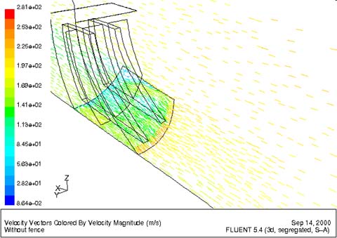
Figure 3
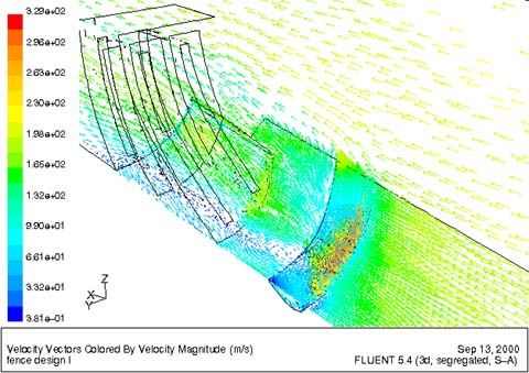
Figure 4
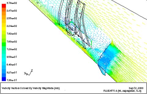
Figure 5
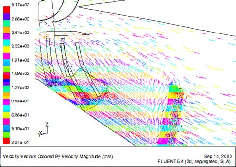
Figure 6
Figures 3 through 6 show the effect of the fence on the airflow pattern around the APU inlet. Without fence, Figure 3 illustrates the air flow is parallel to the airplane axial direction. By adding the fence design I, a re-circulation zone is found behind the fence. Figure 4 indicates that the re-circulation zone results in low momentum air flowing into the center region of the APU inlet. By changing the shape of the fence, Figure 5 shows the re-circulation zone moves to the side of the APU inlet for Design II. When moving the fence 16 inches forward, Figure 6 shows that the airflow is well attached to the airplane wall before it reached to the APU inlet.
"This inlet was a big design challenge for us, with so many parameters that could vary and the performance requirements being so critical," says Jose. "It would have been very difficult to do without a powerful CFD tool. Even if we had come up with a design that worked, we would not have been able to optimize it the way we did. Tools such as virtual geometry and unstructured meshing were key in this application because they made the use of CFD possible."
For more information, contact: Fluent Inc., 10 Cavendish Court, Centerra Resource Park, Lebanon, NH 03766. Ph: 603-643-2600, Fax: 603-643-3967. Visit Fluent's web site at http://www.fluent.com